Appendix XIX B. Glass Containers for Pharmaceutical Use
Glass containers for pharmaceutical use are glass articles intended to come into direct contact with pharmaceutical preparations.
Colourless glass is highly transparent in the visible spectrum.
Coloured glass is obtained by the addition of small amounts of metal oxides, chosen according to the desired spectral absorbance.
Neutral glass is a borosilicate glass containing significant amounts of boric oxide, aluminium oxide, alkali metal oxides and/or alkaline earth oxides in the glass network. Due to its composition, neutral glass has a high hydrolytic resistance and a high thermal shock resistance.
Soda-lime-silica glass is a silica glass containing alkali metal oxides, mainly sodium oxide, and alkaline earth oxides, mainly calcium oxide, in the glass network. Due to its composition, soda-lime-silica glass has only a moderate hydrolytic resistance.
The hydrolytic stability of glass containers for pharmaceutical use is expressed by the resistance to the release of soluble mineral substances into water under the prescribed conditions of contact between the inner surface of the container or glass grains and water. The hydrolytic resistance is evaluated by titrating released alkali reacting ions. According to their hydrolytic resistance, glass containers are classified as follows:
The following italicised statements constitute general recommendations concerning the type of glass container that may be used for different types of pharmaceutical preparations. The manufacturer of a pharmaceutical product is responsible for ensuring the suitability of the chosen container.
Type I glass containers are suitable for most preparations whether or not for parenteral administration.
Type II glass containers are suitable for most acidic and neutral, aqueous preparations whether or not for parenteral administration.
Type III glass containers are in general suitable for non-aqueous preparations for parenteral administration, for powders for parenteral administration (except for freeze-dried preparations) and for preparations not for parenteral administration.
Glass containers with a hydrolytic resistance higher than that recommended above for a particular type of preparation may generally also be used.
The container chosen for a given preparation shall be such that the glass material does not release substances in quantities sufficient to affect the stability of the preparation or to present a risk of toxicity. In justified cases, further detailed information may be necessary to assess the impact on chronic use and for vulnerable patient groups.
Preparations for parenteral administration are normally presented in colourless glass, but coloured glass may be used for substances known to be light-sensitive. Colourless or coloured glass is used for the other pharmaceutical preparations. It is recommended that all glass containers for liquid preparations and for powders for parenteral administration permit the visual inspection of the contents.
The inner surface of glass containers may be specially treated to improve hydrolytic resistance, to confer water-repellancy, etc. The outer surface may also be treated, for example to reduce friction and to improve resistance to abrasion. The outer treatment is such that it does not contaminate the inner surface of the container.
Except for type I glass containers, glass containers for pharmaceutical preparations are not to be re-used. Containers for human blood and blood components must not be re-used.
PRODUCTION
When glass containers for pharmaceutical use are manufactured under stressed conditions (e.g. temperature-time profile) and/or are placed in contact with particularly aggressive pharmaceutical preparations, they may undergo delamination, i.e the separation of the inner glass surface into thin layers called lamellae or flakes. Glass delamination may be the result of a chemical attack that occurs according to well-known glass corrosion mechanisms, such as dissolution by hydrolysis and ion exchange (leaching) as a function of the pH. The process of interaction between the glass surface and the pharmaceutical preparation requires incubation time, and flaking may only become visible a number of months after filling.
Several risk factors are known to increase the propensity of a glass to delaminate. The chemical composition of the pharmaceutical preparation, the presence of buffers like citrate or phosphate, which are known to corrode glass, and the ionic strength of the liquid medium may all strongly favour delamination. The manufacturing process of the container, chemical treatments of the inner surface, and terminal sterilisation and processing at the pharmaceutical filling lines are other important risk factors to be considered. It is recommended that the user of the container assesses the compatibility of the glass container and the pharmaceutical preparation on a case-by-case basis, considering for example the dosage form, properties of the formulation and glass quality.
The propensity to delamination of glass containers from different sources can be assessed and ranked by exposing the container to accelerated degradation testing, carried out at specified temperatures for a short time and using the solutions associated with the actual pharmaceutical preparation as extractants. The presence of particles in the extraction solution, the occurrence of phase separation on the inner surface, and the steep increase of silica concentration in the extraction solution are all indicators of a potential propensity for delamination. Accelerated degradation testing can be used as a predictive tool to select the most appropriate container for the intended preparation, but the full compatibility of the active substance with the glass leachate can only be assessed by a stability test under normal conditions of use.
TESTS
Glass containers for pharmaceutical use comply with the relevant test or tests for hydrolytic resistance. When glass containers have non-glass components, the tests apply only to the glass part of the container.
To define the quality of glass containers according to the intended use, one or more of the following tests are necessary.
Tests for hydrolytic resistance are carried out to define the type of glass (I, II or III) and to control its hydrolytic resistance.
In addition, containers for aqueous parenteral preparations are tested for arsenic release and coloured glass containers are tested for spectral transmission.
HYDROLYTIC RESISTANCE
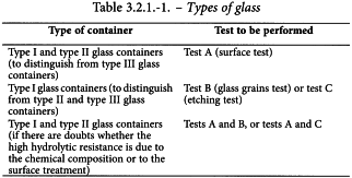
The test is carried out by titration of the extraction solutions obtained under the conditions described for tests A, B and C. Test C is performed if there are uncertainties whether the container is type I or type II.
Equipment
Flasks and beakers shall have been already used for the test or have been filled with water R and kept in an autoclave at 121 °C at least for 1 h before being used.
Determination of the filling volume
The filling volume is the volume of water to be introduced into the container for the purpose of the test. For vials and bottles the filling volume is 90 per cent of the brimful capacity. For ampoules it is the volume up to the height of the shoulder.
Vials and bottles
Select, at random, 6 containers from the sample lot, or 3 if their capacity exceeds 100 mL, and remove any debris or dust. Weigh the empty containers with an accuracy of 0.1 g. Place the containers on a horizontal surface and fill them with water R until about the rim edge, avoiding overflow and introduction of air bubbles. Adjust the liquid levels to the brimful line. Weigh the filled containers to obtain the mass of the water expressed to 2 decimal places for containers having a nominal volume less than or equal to 30 mL, and expressed to 1 decimal place for containers having a nominal volume greater than 30 mL. Calculate the mean value of the brimful capacity in millilitres and multiply it by 0.9. This volume, expressed to 1 decimal place, is the filling volume for the particular container lot.
Ampoules
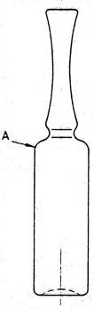
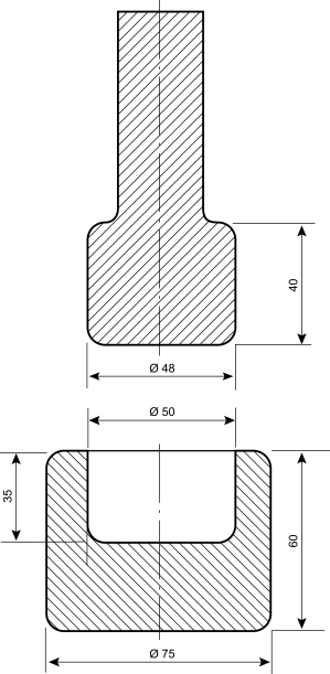
Place at least 6 dry ampoules on a flat, horizontal surface and fill them with water R from a burette, until the water reaches point A, where the body of the ampoule declines to the shoulder (see Figure 3.2.1.-1). Read the capacities (expressed to 2 decimal places) and calculate the mean value. This volume, expressed to 1 decimal place, is the filling volume for the particular ampoule lot. The filling volume may also be determined by weighing.
Syringes and cartridges
Select 6 syringes or cartridges. Close the small opening (mouth of cartridges and needle and/or Luer cone of syringes) using an inert material (e.g. a tip cap). Determine the mean brimful volume in accordance with the procedure described under Vials and bottles and multiply it by 0.9. This volume, expressed to 1 decimal place, is the filling volume for the particular container lot.
Test A. Hydrolytic resistance of the inner surfaces of glass containers (surface test)
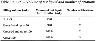
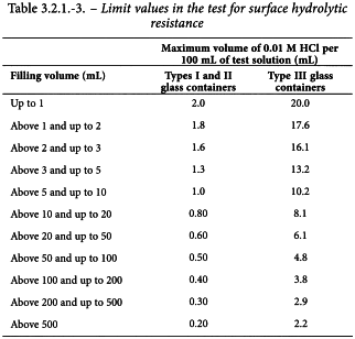
The determination is carried out on unused containers. The volumes of the test liquid necessary are indicated in Table 3.2.1.-2.
Cleaning
Remove any debris or dust. Shortly before the test, carefully rinse each container at least twice with water R. Immediately before testing the drained containers, rinse once with water R then with water R1 and allow to drain. Complete the cleaning procedure from the 1st rinsing within 20-30 min.
Closed ampoules shall not be rinsed before testing. Closed ampoules can be warmed on a water bath or in an air-oven at about 40 °C for approximately 2 min before opening to avoid underpressure when opening.
Filling and heating
Fill the containers with water R1 up to the filling volume.
Loosely cap each container with an inert material, for example with inverted beakers of such a size that the bottoms of the beakers fit snugly down on the rims of the sample. Ampoules and vials capped with clean aluminium foil are further examples. Place syringes and cartridges in a beaker and cover the beaker with clean aluminium foil.
Place the samples, gathered in groups in glass dishes or in beakers or other suitable holders, on the rack in the autoclave containing water R at room temperature. Ensure that they are held above the level of the water in the autoclave.
Insert the end of an externally calibrated thermometric device into a filled container through a hole of approximately the diameter of the thermocouple and connect it to an external measuring device. If the container is too small to insert a thermocouple, apply a thermocouple in a similar container of suitable size. Close the autoclave door or lid securely but leave the vent-cock open. Start automatic recording of the temperature versus time and heat the autoclave at a regular rate such that steam issues vigorously from the vent-cock after 20-30 min, and maintain a vigorous evolution of steam for a further 10 min. Where a steam autoclave is used, it is not necessary to maintain the temperature for 10 min at 100 °C.
Close the vent-cock and raise the temperature from 100 °C to 121 °C at a rate of 1 °C/min within 20-22 min. Maintain the temperature at 121 ± 1 °C for 60 ± 1 min from the time when the holding temperature was reached. Cool to 100 °C at a rate of 0.5 °C/min within 40-44 min, venting to prevent formation of a vacuum. Remove the hot samples from the autoclave and cool cautiously to room temperature within 30 min.
Method
Carry out the titration within 1 h of removal of the containers from the autoclave. Combine the liquids obtained from the containers and mix. Introduce the prescribed volume (Table 3.2.1.-2) into a conical flask (test solution). Place the same volume of water R1 into a 2nd similar flask as a blank. Add to each flask 0.05 mL of methyl red solution R for each 25 mL of liquid. Titrate the blank with 0.01 M hydrochloric acid. Titrate the test solution with the same acid until the colour of the resulting solution is the same as that obtained for the blank. Subtract the value found for the blank titration from that found for the test solution and express the results in millilitres of 0.01 M hydrochloric acid per 100 mL. Express titration values of less than 1.0 mL to 2 decimal places and titration values of more than or equal to 1.0 mL to 1 decimal place.
Limits
The results, or the average of the results if more than 1 titration is performed, is not greater than the values stated in Table 3.2.1.-3.
test B. hydrolytic resistance of glass grains (glass grains test)
Check that the articles as received have been annealed to a commercially acceptable quality.
The test may be performed on the canes used for the manufacture of tubing glass containers or on the containers.
Equipment
Method
Rinse the containers to be tested with water R and dry in the oven. Wrap at least 3 of the glass articles in clean paper and crush to produce 2 samples of about 100 g each, in pieces not more than 30 mm across.
Where a mortar, pestle and hammer are used, place in the mortar 30-40 g of the pieces 10-30 mm across taken from 1 of the samples, insert the pestle and strike it heavily, once only, with the hammer. Transfer the contents of the mortar to sieve (a), the coarsest of the set. Repeat the operation until all fragments have been transferred to the sieve. Shake the set of sieves for a short time by hand and remove the glass that remains on sieves (a) and (b). Submit these portions to further fracture, repeating the operation until about 10 g of glass remains on sieve (a). Reject this portion and the portion that passes through sieve (c). Reassemble the set of sieves and shake for 5 min. Transfer to a weighing bottle those glass grains that pass through sieve (b) and are retained on sieve (c).
Where a ball mill is used, place in the ball mill beaker about 50 g of the pieces 10-30 mm across taken from 1 of the samples, add the balls and crush thin-walled glass (wall thickness up to 1.5 mm) for up to 2 min and thick-walled glass (wall thickness greater than 1.5 mm) for up to 5 min. Transfer the grains to sieve (a), sieve for about 30 s and collect the grains retained on sieve (c). Transfer the glass from sieves (a) and (b) into the ball mill and crush and sieve again as indicated above. Combine the grains retained on sieve (c).
Repeat the crushing and sieving procedure with the other glass sample and thus 2 samples of grains, each of which shall be in excess of 10 g, are obtained. Spread each sample on a piece of clean glazed paper and remove any iron particles by passing the magnet over them. Transfer each sample into a beaker for cleaning. Add to the grains in each beaker 30 mL of acetone R and scour the grains by suitable means, such as a rubber- or plastic-coated glass rod. After scouring the grains, allow to settle and decant as much acetone as possible. Add another 30 mL of acetone R, swirl, allow to settle and decant again, and add 30 mL of acetone R.
Fill the bath of the ultrasonic vessel with water at room temperature, then place the beaker in the rack and immerse it until the level of the acetone is at the level of the water; apply the ultrasound for 1 min. Swirl the beaker, allow to settle and decant the acetone as completely as possible, add 30 mL of acetone R and repeat the ultrasonic cleaning operation. If a fine turbidity persists, repeat the ultrasonic cleaning and acetone washing until the solution remains clear. Swirl and decant the acetone then dry the grains, first by putting the beaker on a warm plate to remove excess acetone and then by heating at 140 °C for 20 min in the drying oven. Transfer the dried grains from each beaker into separate weighing bottles, insert the stoppers and cool in the desiccator. Weigh 10.00 g of the cleaned and dried grains into 2 separate conical flasks. Add 50 mL of water R1 into each by means of a pipette (test solutions). Pipette 50 mL of water R1 into a 3rd conical flask as a blank. Distribute the grains evenly over the flat bases of the flasks by gentle shaking. Close the flasks with neutral glass dishes or aluminium foil rinsed with water R, or with inverted beakers so that the inner surface of the beakers fit snugly down onto the top rims of the flasks. Place all 3 flasks in the rack in the autoclave containing the water at room temperature, and ensure that they are held above the level of the water in the vessel. Carry out the autoclaving procedure in a similar manner to that described under test A, but maintain the temperature of 121 ± 1 °C only for 30 ± 1 min. Do not open the autoclave until it has cooled to 95 °C. Remove the hot samples from the autoclave and cool the flasks in running tap water as soon as possible, avoiding thermal shock. To each of the 3 flasks add 0.05 mL of methyl red solution R. Titrate the blank solution immediately with 0.02 M hydrochloric acid then titrate the test solutions with the same acid until the colour matches that obtained with the blank solution. Subtract the titration volume for the blank solution from that for the test solution.
NOTE: where necessary to obtain a sharp end-point, the clear solution is to be decanted into a separate 250 mL flask. Rinse the grains with 3 quantities, each of 15 mL, of water R1 by swirling and add the washings to the main solution. Add 0.05 mL of methyl red solution R. Titrate and calculate as described below. In this case also add 45 mL ofwater R1 and 0.05 mL of methyl red solution R to the blank solution.
Calculate the mean value of the results in millilitres of 0.02 M hydrochloric acid per gram of the sample and if required its equivalent in alkali extracted, calculated as micrograms of sodium oxide per gram of glass grains.
1 mL of 0.02 M hydrochloric acid is equivalent to 620 µg of sodium oxide.
Repeat the test if the highest and lowest observed values differ by more than 20 per cent.
Limits
Type I glass containers require not more than 0.1 mL of 0.02 M hydrochloric acid per gram of glass, type II and type III glass containers require not more than 0.85 mL of 0.02 M hydrochloric acid per gram of glass.
test C. to determine whether the containers have been surface-treated (etching test)
If there are uncertainties whether a container has been surface-treated, and/or to distinguish between type I and type II glass containers, test C is used in addition to test A. Alternatively, tests A and B may be used. Test C may be carried out either on unused samples or on samples previously used in test A.
Vials and bottles
The volumes of test liquid required are shown in Table 3.2.1.-2.
Rinse the containers twice with water R, fill to the brimful point with a mixture of 1 volume of hydrofluoric acid R and 9 volumes of hydrochloric acid R and allow to stand for 10 min. Empty the containers and rinse carefully 5 times with water R. Immediately before the test, rinse once again with water R. Submit the containers thus prepared to the same autoclaving and determination procedure as described in Test A for surface hydrolytic resistance. If the results are considerably higher than those obtained from the original surfaces (by about a factor of 5 to 10), the samples have been surface-treated.
Ampoules, cartridges and syringes
NOTE: ampoules, cartridges and syringes made from glass tubing are not normally subjected to internal surface treatment because their high chemical resistance is dependent upon the chemical composition of the glass as a material.
Apply the test method as described above for vials and bottles. If the ampoules are not surface-treated, the new values are slightly lower than those obtained in previous tests.
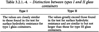
Distinction between type I and type II glass containers
The results obtained in Test C are compared to those obtained in Test A. The interpretation of the result is shown in Table 3.2.1.-4.
ARSENIC
The test applies to glass containers for aqueous parenteral preparations.
Hydride generation atomic absorption spectrometry (2.2.23, Method I).
Test solution Use the extraction solution obtained from containers of types I and II, after autoclaving at 121 °C for 1 h as described under Test A for surface hydrolytic resistance. Transfer 10.0 mL to a 100 mL volumetric flask. Add 10 mL of hydrochloric acid R and 5 mL of a 200 g/L solution of potassium iodide R. Heat on a water-bath at 80 °C for 20 min, allow to cool and dilute to 100.0 mL with water R.
Reference solutions Prepare the reference solutions using arsenic standard solution (1 ppm As) R. Add 10 mL of hydrochloric acid R and 5 mL of a 200 g/L solution of potassium iodide R. Heat on a water-bath at 80 °C for 20 min, allow to cool and dilute to 100.0 mL with water R. The concentration range of the reference solutions is typically 0.005-0.015 ppm of As.
Acid reservoirHydrochloric acid R.
Reducing reservoirSodium tetrahydroborate reducing solution R.
Use a hydride generation device to introduce the test solution into the cuvette of the spectrometer. Establish and standardise instrumental operating conditions according to the manufacturer’s instructions, optimise the uptake rate of the peristaltic pump, then connect it to the acid reservoir, the reducing reservoir and the test solution.
Source Hollow-cathode lamp.
Wavelength 193.7 nm.
Atomisation device Air-acetylene flame.
Limit Maximum 0.1 ppm of As.
SPECTRAL TRANSMISSION FOR COLOURED GLASS CONTAINERS
Equipment
A UV-Vis spectrophotometer, equipped with a photodiode detector or equipped with a photomultiplier tube coupled with an integrating sphere.
Preparation of the specimen
Break the glass container or cut it with a circular saw fitted with a wet abrasive wheel, such as a carborundum or a bonded-diamond wheel. Select sections representative of the wall thickness and trim them as suitable for mounting in a spectrophotometer. If the specimen is too small to cover the opening in the specimen holder, mask the uncovered portion with opaque paper or tape, provided that the length of the specimen is greater than that of the slit. Before placing in the holder, wash, dry and wipe the specimen with a lens tissue. Mount the specimen with the aid of wax, or by other convenient means, taking care to avoid leaving fingerprints or other marks.
Method
Place the specimen in the spectrophotometer with its cylindrical axis parallel to the slit and in such a way that the light beam is perpendicular to the surface of the section and that the losses due to reflection are at a minimum. Measure the transmission of the specimen with reference to air in the spectral region of 290-450 nm, continuously or at intervals of 20 nm.
Limits
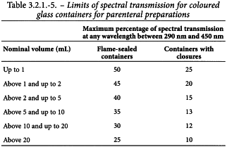
The observed spectral transmission for coloured glass containers for preparations that are not for parenteral administration does not exceed 10 per cent at any wavelength in the range of 290-450 nm, irrespective of the type and the capacity of the glass container. The observed spectral transmission in coloured glass containers for parenteral preparations does not exceed the limits given in Table 3.2.1.-5.
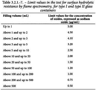
Annex – test for surface hydrolytic resistance – determination by flame spectrometry
The surface hydrolytic resistance of glass of types I and II may be determined by analysis of the leaching solution by flame spectrometry. A number of elements that, when present as oxides in glass, contribute to the alkalinity of the solution, are determined and used to express an alkali equivalent. The spectrometric method has the advantage of allowing the use of a much smaller sample of extract so that it can be applied to small individual containers. This enables an evaluation of the uniformity of the containers in a given batch where this is critical. The results of this measurement are not equivalent to those of titrimetry and the 2 methods cannot be considered interchangeable. A correlation between the 2 is dependent on the type of glass and the size and shape of the container. The titrimetric method is the reference method of the Pharmacopoeia; the spectrometric method may be used in justified and authorised cases.
A method suitable for this type of analysis is shown below.
The determination is carried out on unused containers. The number of containers to be examined is indicated in Table 3.2.1.-6.

Instructions on determination of the filling volume, cleaning of the containers, filling and heating are given above under Hydrolytic resistance and Test A.
SOLUTIONS
Spectrochemical buffer solution Dissolve 80 g of caesium chloride R in about 300 mL of water R1, add 10 mL of 6 M hydrochloric acid R, dilute to 1.0 L with water R1 and mix.
Commercially available stock solutions may also be used.
Standard solutions Prepare standard solutions by diluting the stock solutions with water R1 to obtain concentrations suitable for establishing the reference solutions in an appropriate manner, e.g. with concentrations of 20 µg/mL of sodium oxide, potassium oxide and calcium oxide, respectively. Commercially available standard solutions may also be used.
Reference solutions Prepare the reference solutions for establishing the calibration graph (set of calibration solutions) by diluting suitable concentrated standard solutions with water R1, so that the normal working ranges of the specific elements are covered, taking into account the instrument used for the measurement. Typical concentration ranges of the reference solutions are:
Use reference solutions containing 5 per cent V/V of the spectrochemical buffer solution.
Method
Carry out preliminary measurements of the potassium oxide and calcium oxide concentrations on one of the extraction solutions. If, for one container type, the concentration of potassium oxide is less than 0.2 µg/mL and the concentration of calcium oxide is less than 0.1 µg/mL, the remaining extraction solutions of this container type need not be analysed for these ions. Aspirate the extraction solution from each sample directly into the flame of the atomic absorption or atomic emission instrument and determine the approximate concentrations of sodium oxide (and potassium oxide and calcium oxide, if present) by reference to calibration graphs produced from the reference solutions of suitable concentration.
Final ANALYSIS
If dilution is unnecessary, add to each container a volume of the spectrochemical buffer solution equivalent to 5 per cent of the filling volume, mix well and determine sodium oxide, calcium oxide and potassium oxide, by reference to calibration graphs. For the determination of the calcium oxide concentration by flame spectrometry, a nitrous oxide/acetylene flame shall be used.
If dilution is necessary, determine sodium oxide, calcium oxide and potassium oxide, if present, following the procedures as described above. The solutions shall contain 5 per cent V/V of the spectrochemical buffer solution. Concentration values less than 1.0 µg/mL are expressed to 2 decimal places, values greater than or equal to 1.0 µg/mL to 1 decimal place. Correct the result for the buffer addition and for any dilution.
DETERMINATION
Determine the mean value of the concentration of individual oxides found in the samples tested, in micrograms of the oxide per millilitre of the extraction solution, and calculate the sum of the individual oxides, expressed as micrograms of sodium oxide per millilitre of the extraction solution, using the following mass conversion factors:
Limits
The mean value is not greater than the value given in Table 3.2.1.-7.