Appendix IX E. Limit Test for Carbon Monoxide in Medicinal Gases
METHOD I
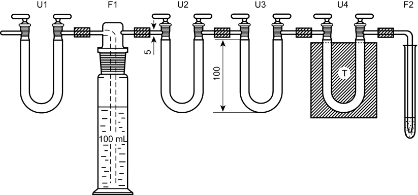
Apparatus The apparatus (Figure 2.5.25.-1) consists of the following parts connected in series:
Method Flush the apparatus with 5.0 L of argon R and, if necessary, discharge the blue colour in the iodide solution by adding the smallest necessary quantity of freshly prepared 0.002 M sodium thiosulfate. Continue flushing until not more than 0.045 mL of 0.002 M sodium thiosulfate is required after passage of 5.0 L of argon R. Pass the gas to be examined from the cylinder through the apparatus, using the prescribed volume and the flow rate. Flush the last traces of liberated iodine into the reaction tube by passing through the apparatus 1.0 L of argon R. Titrate the liberated iodine with 0.002 M sodium thiosulfate. Carry out a blank test, using the prescribed volume of argon R. The difference between the volumes of 0.002 M sodium thiosulfate used in the titrations is not greater than the prescribed limit.
METHOD II
Gases absorb light at one or more specific wavelengths. This property is widely used to allow highly selective measurement of their concentrations.
Description and principle of measurement
The concentration of carbon monoxide in other gases can be determined using an infrared analyser.
The infrared analyser generally consists of a light source emitting broadband infrared radiation, an optical device, a sample cell and a detector. The optical device may be positioned either before or after the sample cell; it consists of one or several optical filters, through which the broadband radiation is passed. The optical device in this case is selected for carbon monoxide. The measurement light beam passes through the sample cell and may also pass through a reference cell if the analyser integrates such a feature (some use an electronic system instead of a reference cell).
When carbon monoxide is present in the sample cell, absorption of energy in the measurement light beam will occur according to the Beer-Lambert law and this produces a change in the detector signal. This measurement signal is compared to a reference signal to generate an output related to the concentration of carbon monoxide. The generated signal is linearised in order to obtain the carbon monoxide concentration. To prevent the entry of particles into the sensors, which could cause stray-light phenomena, the apparatus is fitted with a suitable filter.
Required technical specifications
When used for a limit test, the carbon monoxide infrared analyser meets the following technical specifications:
The technical specifications must be met in the presence of the other gas impurities in the sample.