Appendix XVII C. Specific Surface Area by Air Permeability
The test is intended for the determination of the specific surface area of dry powders expressed in square metres per gram in the sub-sieve region. The effect of molecular flow (“slip flow”) which may be important when testing powders consisting of particles less than a few micrometres is not taken into account in the equation used to calculate the specific surface area.
APPARATUS
The apparatus consists of the following parts:
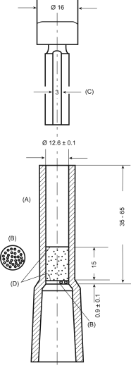
(a) a permeability cell (see Figure 2.9.14.-1), which consists of a cylinder with an inner diameter of 12.6 ± 0.1 mm (A), constructed of glass or non-corroding metal. The bottom of the cell forms an airtight connection (for example, via an adapter) with the manometer (Figure 2.9.14.-2). A ledge 0.5-1 mm in width is located 50 ± 15 mm from the top of the cell. It is an integral part of the cell or firmly fixed so as to be airtight. It supports a perforated metal disk (B), constructed of non-corroding metal. The disk has a thickness of 0.9 ± 0.1 mm and is perforated with 30 to 40 holes 1 mm in diameter evenly distributed over this area.
The plunger (C) is made of non-corroding metal and fits into the cell with a clearance of not more than 0.1 mm. The bottom of the plunger has sharp square edges at right angles to the principal axis. There is an air vent 3 mm long and 0.3 mm deep on one side of the plunger. The top of the plunger has a collar such that when the plunger is placed in the cell and the collar is brought into contact with the top of the cell, the distance between the bottom of the plunger and the top of the perforated disk (B) is 15 ± 1 mm.
The filter paper disks (D) have smooth edges and the same diameter as the inside of the cell.
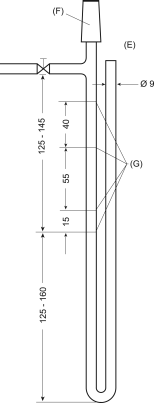
(b) a U-tube manometer (E) (Figure 2.9.14.-2) is made of nominal 9 mm outer diameter and 7 mm inner diameter glass tubing with standard walls. The top of one arm of the manometer forms an airtight connection with the permeability cell (F). The manometer arm connected to the permeability cell has a line etched around the tube at 125-145 mm below the top of the side outlet and three other lines at distances of 15 mm, 70 mm and 110 mm above that line (G). The side outlet, 250-305 mm above the bottom of the manometer, is used to evacuate the manometer arm connected to the permeability cell. A tap is provided on the side outlet not more than 50 mm from the manometer arm.
The manometer is mounted firmly in such a manner that the arms are vertical. It is filled to the lowest mark with the liquid recommended by the manufacturer of the equipment or water.
METHOD
If prescribed, dry the powder to be examined and sift through a suitable sieve (for example no. 125) to disperse agglomerates. Calculate the mass (M) of the powder to be used from the following expression:

| V | = | bulk volume of the compacted bed of powder, |
| ρ | = | density of the substance to be examined in grams per millilitre, |
| ε | = | porosity of the compacted bed of powder. |
Assume first a porosity of 0.5 and introduce this value in expression (1) to calculate the mass (M) of the powder to be examined.
Place a filter paper disk on top of the perforated metal disk (B). Weigh the calculated mass (M) of the powder to be examined to the nearest 1 mg. Carefully transfer the powder into the cleaned, tared permeability cell and carefully tap the cell so that the surface of the powder bed is level and cover it with a second filter paper disk. Slowly compact the powder by means of the plunger, avoiding rotary movement. Maintain the pressure until the plunger is completely inserted into the permeability cell. If this is not possible, decrease the quantity of the powder used. If, on the contrary, there is not enough resistance, increase the quantity of the powder. In this case calculate the porosity again. After at least 10 s, remove the plunger.
Attach the permeability cell to the tube of the manometer by means of an airtight connection. Evacuate the air from the manometer by means of a rubber bulb until the level of the coloured liquid is at the highest mark. Close the tap and check that the apparatus is airtight by closing the upper end of the cell, for example with a rubber stopper. Remove the stopper and, using a timer, measure the time taken for the liquid to fall from the second to the third mark.
Using the measured flow time, calculate the specific surface area (S), expressed in square metres per gram, from the following expression:

| t | = | flow time in seconds, |
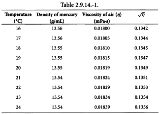
| η | = | dynamic viscosity of air in millipascal seconds (see Table 2.9.14.-1), |
| K | = | apparatus constant determined according to expression (4), |
| ρ | = | density of the substance to be examined in grams per millilitre, |
| ε | = | porosity of the compacted bed of powder. |
CALIBRATION OF THE APPARATUS
Bulk volume of the compacted powder bed
It is determined by the mercury displacement method as follows:
Place two filter paper disks in the permeability cell, pressing down the edges with a rod slightly smaller than the cell diameter until the filter disks lie flat on the perforated metal disk; fill the cell with mercury, removing any air bubbles adhering to the wall of the cell and wipe away the excess to create a plane surface of mercury at the top of the cell. If the cell is made of material that will amalgamate, grease the cell and the metal disk first with a thin layer of liquid paraffin. Pour out the mercury into a tared beaker and determine the mass (MA) and the temperature of the mercury.
Make a compacted bed using the reference powder and again fill the cell with mercury with a planar surface at the top of the cell. Pour out the mercury in a tared beaker and again determine the mass of the mercury (MB). Calculate the bulk volume (V) of the compacted bed of powder from the following expression:
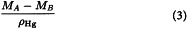
| MA-MB | = | difference between the determined masses of mercury in grams, |
| ρHg | = | density of mercury at the determined temperature in grams per millilitre. |
Repeat the procedure twice, changing the powder each time; the range of values for the calculated volume (V) is not greater than 0.01 mL. Use the mean value of the three determined volumes for the calculations.
Apparatus constant (K)
It is determined using a reference powder with known specific surface area and density as follows:
Calculate the required quantity of the reference powder to be used (expression (1)) using the stated density and the determined volume of the compacted powder bed (expression (3)).
Homogenise and loosen up the powder by shaking it for 2 min in a 100 mL bottle. Prepare a compacted powder bed and measure the flow time of air as previously described. Calculate the apparatus constant (K) from the following expression:
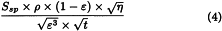
| Ssp | = | stated specific surface area of the reference powder, |
| ρ | = | density of the substance to be examined in grams per millilitre, |
| ε | = | porosity of the compacted bed of powder, |
| t | = | flow time in seconds, |
| η | = | dynamic viscosity of air in millipascal seconds (see Table 2.9.14.-1). |
The density of mercury and the viscosity of air over a range of temperatures are shown in Table 2.9.14.-1.