Appendix III F. Electrophoresis1
♦1 GENERAL PRINCIPLE
Under the influence of an electrical field, charged particles dissolved or dispersed in an electrolyte solution migrate in the direction of the electrode bearing the opposite polarity. In gel electrophoresis, the movements of the particles are retarded by interactions with the surrounding gel matrix, which acts as a molecular sieve. The opposing interactions of the electrical force and molecular sieving result in differential migration rates according to sizes, shapes and charges of particles. Because of their different physico-chemical properties, different macromolecules of a mixture will migrate at different speeds during electrophoresis and will thus be separated into discrete fractions. Electrophoretic separations can be conducted in systems without support phases (e.g. free solution separation in capillary electrophoresis) and in stabilising media such as thin-layer plates, films or gels.
2 FREE OR MOVING BOUNDARY ELECTROPHORESIS
This method is mainly used for the determination of mobility, the experimental characteristics being directly measurable and reproducible. It is chiefly employed with substances of high relative molecular mass and low diffusibility. The boundaries are initially located by a physical process such as refractometry or conductimetry. After applying a given electric field for an accurately measured time, the new boundaries and their respective positions are observed. The operating conditions must be such as to make it possible to determine as many boundaries as there are components.
3 ZONE ELECTROPHORESIS USING A SUPPORTING MEDIUM
This method requires the use of small samples only.
The nature of the support, such as paper, agar gel, cellulose acetate, starch, agarose, methacrylamide, mixed gel, introduces a number of additional factors modifying the mobility:
The rate of migration then depends on four main factors: the mobility of the charged particle, the electro-endosmotic flow, the evaporation flow, and the field strength. Hence it is necessary to operate under clearly defined experimental conditions and to use, wherever possible, reference substances.
An apparatus for electrophoresis consists of:
The electrophoresis chamber is fitted with an airtight lid which maintains a moisture-saturated atmosphere during operation and reduces evaporation of the solvent. A safety device may be used to cut off the power when the lid is removed. If the electrical power measured across the strip exceeds 10 W, it is preferable to cool the support.
Strip electrophoresis The supporting strip, previously wetted with the same conducting solution and dipped at each end into an electrode compartment is appropriately tightened and fixed on to a suitable carrier designed to prevent diffusion of the conducting electrolyte, such as a horizontal frame, inverted-V stand or a uniform surface with contact points at suitable intervals.
Gel electrophoresis The device consists essentially of a glass plate (for example, a microscope slide) over the whole surface of which is deposited a firmly adhering layer of gel of uniform thickness. The connection between the gel and the conducting solution is effected in various ways according to the type of apparatus used. Precautions must be taken to avoid condensation of moisture or drying of the solid layer.
Method Introduce the electrolyte solution into the electrode compartments. Place the support suitably impregnated with electrolyte solution in the chamber under the conditions prescribed for the type of apparatus used. Locate the starting line and apply the sample. Apply the electric current for the prescribed time. After the current has been switched off, remove the support from the chamber, dry and visualise.
4 POLYACRYLAMIDE ROD GEL ELECTROPHORESIS
In polyacrylamide rod gel electrophoresis, the stationary phase is a gel which is prepared from a mixture of acrylamide and N,N′-methylenebisacrylamide. Rod gels are prepared in tubes 7.5 cm long and 0.5 cm in internal diameter, one solution being applied to each rod.
Apparatus This consists of 2 buffer solution reservoirs made of suitable material such as poly(methyl methacrylate) and mounted vertically one above the other. Each reservoir is fitted with a platinum electrode. The electrodes are connected to a power supply allowing operation either at constant current or at constant voltage. The apparatus has in the base of the upper reservoir a number of holders equidistant from the electrode.
Method The solutions should usually be degassed before polymerisation and the gels used immediately after preparation. Prepare the gel mixture as prescribed and pour into suitable glass tubes, stoppered at the bottom, to an equal height in each tube and to about 1 cm from the top, taking care to ensure that no air bubbles are trapped in the tubes. Cover the gel mixture with a layer of water R to exclude air and allow to set. Gel formation usually takes about 30 min and is complete when a sharp interface appears between the gel and the water layer. Remove the water layer. Fill the lower reservoir with the prescribed buffer solution and remove the stoppers from the tubes. Fit the tubes into the holders of the upper reservoir and adjust so that the bottom of the tubes are immersed in the buffer solution in the lower reservoir. Carefully fill the tubes with the prescribed buffer solution. Prepare the test and reference solutions containing the prescribed marker dye and make them dense by dissolving in them sucrose R, for example. Apply the solutions to the surface of a gel using a different tube for each solution. Add the same buffer to the upper reservoir. Connect the electrodes to the power supply and allow electrophoresis to proceed at the prescribed temperature and using the prescribed constant voltage or current. Switch off the power supply when the marker dye has migrated almost into the lower reservoir. Immediately remove each tube from the apparatus and extrude the gel. Locate the position of the bands in the electropherogram as prescribed.♦
5 SODIUM DODECYL SULFATE POLYACRYLAMIDE GEL ELECTROPHORESIS (SDS-PAGE)
5-1 SDS-PAGE - UNIFORM PERCENTAGE GELS
Scope
Polyacrylamide gel electrophoresis is used for the qualitative characterisation of proteins in biological preparations, for control of purity and for quantitative determinations.
Purpose
Analytical gel electrophoresis is an appropriate method with which to identify and to assess the homogeneity of proteins in pharmaceutical preparations. The method is routinely used for the estimation of protein subunit molecular masses and for determination of the subunit compositions of purified proteins.
Ready-to-use gels and reagents are commercially available and can be used instead of those described in this text, provided that they give equivalent results and that they meet the validity requirements given below under Validation of the test.
5-1-1 Characteristics of polyacrylamide gels
The sieving properties of polyacrylamide gels are established by the three-dimensional network of fibres and pores which is formed as the bifunctional bisacrylamide cross-links adjacent polyacrylamide chains. Polymerisation is usually catalysed by a free radical-generating system composed of ammonium persulfate and N,N,N′,N′-tetramethylethylenediamine (TEMED).
As the acrylamide concentration of a gel increases, its effective pore size decreases. The effective pore size of a gel is operationally defined by its sieving properties, i.e. by the resistance it imparts to the migration of macromolecules. There are limits on the acrylamide concentrations that can be used. At high acrylamide concentrations, gels break much more easily and are difficult to handle. As the pore size of a gel decreases, the migration rate of a protein through the gel decreases. By adjusting the pore size of a gel, through manipulating the acrylamide concentration, the resolution of the method can be optimised for a given protein product. Thus, a given gel is physically characterised by its respective composition of acrylamide and bisacrylamide.
In addition to the composition of the gel, the state of the protein is an important component to the electrophoretic mobility. In the case of proteins, the electrophoretic mobility is dependent on the pK value of the charged groups and the size of the molecule. It is influenced by the type, the concentration and the pH of the buffer, by the temperature and the field strength, and by the nature of the support material.
5-1-2 Denaturing polyacrylamide gel electrophoresis
The method cited as an example is limited to the analysis of monomeric polypeptides with a mass range of 14 000 to 100 000 daltons. It is possible to extend this mass range using various techniques (e.g. gradient gels, particular buffer system). For instance, tricine-SDS gels, with tricine as the trailing ion in the electrophoresis running-buffer (instead of glycine as in the method described here), can separate very small proteins and peptides under 10 000 to 15 000 daltons.
Denaturing polyacrylamide gel electrophoresis using glycine-SDS is the most common mode of electrophoresis used in assessing the pharmaceutical quality of protein products and will be the focus of the example method. Typically, analytical electrophoresis of proteins is carried out in polyacrylamide gels under conditions that ensure dissociation of the proteins into their individual polypeptide subunits and that minimise aggregation. Most commonly, the strongly anionic detergent SDS is used in combination with heat to dissociate the proteins before they are loaded on the gel. The denatured polypeptides bind to SDS, become negatively charged and exhibit a consistent charge-to-mass ratio regardless of protein type. Because the amount of SDS bound is almost always proportional to the molecular mass of the polypeptide and is independent of its sequence, SDS-polypeptide complexes migrate through polyacrylamide gels with mobilities dependent on the size of the polypeptide.
The electrophoretic mobilities of the resultant detergent- polypeptide complexes all assume the same functional relationship to their molecular masses. SDS complexes will migrate toward the anode in a predictable manner, with low-molecular-mass complexes migrating faster than larger ones. The molecular mass of a protein can therefore be estimated from its relative mobility in calibrated SDS-PAGE, and the intensity of a single band relative to other undesired bands in such a gel can be a measure of purity.
Modifications to the polypeptide backbone, such as N- or O-linked glycosylation, can change the apparent molecular mass of a protein since SDS does not bind to a carbohydrate moiety in a manner similar to a polypeptide; therefore, a consistent charge-to-mass ratio is not maintained.
Depending on the extent of glycosylation and other post-translational modifications, the apparent molecular mass of proteins may not be a true reflection of the mass of the polypeptide chain.
Reducing conditions
Polypeptide subunits and three-dimensional structure are often maintained in proteins by the presence of disulfide bonds. A goal of SDS-PAGE analysis under reducing conditions is to disrupt this structure by reducing disulfide bonds. Complete denaturation and dissociation of proteins by treatment with 2-mercaptoethanol (2-ME) or dithiothreitol (DTT) will result in unfolding of the polypeptide backbone and subsequent complexation with SDS. Using these conditions, the molecular mass of the polypeptide subunits can reasonably be calculated by linear regression (or, more accurately, by non-linear regression) with the aid of suitable molecular-mass standards.
Non-reducing conditions
For some analyses, complete dissociation of the protein into subunit peptides is not desirable. In the absence of treatment with reducing agents such as 2-ME or DTT, disulfide covalent bonds remain intact, preserving the oligomeric form of the protein. Oligomeric SDS-protein complexes migrate more slowly than their SDS-polypeptide subunits. In addition, non-reduced proteins may not be completely saturated with SDS and, hence, may not bind the detergent in a constant mass ratio. Moreover, intra-chain disulfide bonds constrain the molecular shape, usually in such a way as to reduce the Stokes radius of the molecule, thereby reducing the apparent molecular mass Mr. This makes molecular-mass determinations of these molecules by SDS-PAGE less straightforward than analyses of fully denatured polypeptides, since it is necessary that both standards and unknown proteins be in similar configurations for valid comparisons.
5-1-3 Characteristics of discontinuous buffer system gel electrophoresis
The most popular electrophoretic method for the characterisation of complex mixtures of proteins uses a discontinuous buffer system involving 2 contiguous, but distinct gels: a resolving or separating (lower) gel and a stacking (upper) gel. The 2 gels are cast with different porosities, pH, and ionic strengths. In addition, different mobile ions are used in the gel and electrode buffers. The buffer discontinuity acts to concentrate large volume samples in the stacking gel, resulting in improved resolution. When power is applied, a voltage drop develops across the sample solution which drives the proteins into the stacking gel. Glycinate ions from the electrode buffer follow the proteins into the stacking gel. A moving boundary region is rapidly formed with the highly mobile chloride ions in the front and the relatively slow glycinate ions in the rear. A localised high-voltage gradient forms between the leading and trailing ion fronts, causing the SDS-protein complexes to form into a thin zone (stack) and migrate between the chloride and glycinate phases. Within broad limits, regardless of the height of the applied sample, all SDS-proteins condense into a very narrow region and enter the resolving gel as a well-defined, thin zone of high protein density. The large-pore stacking gel does not retard the migration of most proteins and serves mainly as an anti-convective medium. At the interface of the stacking and resolving gels, the proteins undergo a sharp increase in retardation due to the restrictive pore size of the resolving gel and the buffer discontinuity, which also contributes to the focusing of the proteins. Once in the resolving gel, proteins continue to be slowed by the sieving of the matrix. The glycinate ions overtake the proteins, which then move in a space of uniform pH formed by the tris(hydroxymethyl)aminomethane and glycine. Molecular sieving causes the SDS-polypeptide complexes to separate on the basis of their molecular masses.
5-1-4 Preparing vertical discontinuous buffer SDS polyacrylamide gels
This section describes the preparation of gels using particular instrumentation. This does not apply to pre-cast gels. For pre-cast gels or any other commercially available equipment, the manufacturer′s instructions must be used for guidance.
The use of commercial reagents that have been purified in solution is recommended. When this is not the case and where the purity of the reagents used is not sufficient, a pre-treatment is applied. For instance, any solution sufficiently impure to require filtration must also be deionised with a mixed-bed (anion/cation exchange) resin to remove acrylic acid and other charged degradation products. When stored according to recommendations, acrylamide/bisacrylamide solutions and solid persulfate are stable for long periods.
Assembling the gel moulding cassette
Clean the 2 glass plates (e.g. 10 cm by 8 cm in size), the polytetrafluoroethylene comb, the 2 spacers and the silicone rubber tubing (e.g. 0.6 mm in diameter by 35 cm) with mild detergent and rinse extensively with water, followed by anhydrous ethanol, and allow the plates to dry at room temperature. Lubricate the spacers and the tubing with non-silicone grease. Apply the spacers along each of the 2 short sides of the glass plate 2 mm away from the edges and 2 mm away from the long side corresponding to the bottom of the gel. Begin to lay the tubing on the glass plate by using one spacer as a guide. Carefully twist the tubing at the bottom of the spacer and follow the long side of the glass plate. While holding the tubing with 1 finger along the long side, twist again the tubing and lay it on the second short side of the glass plate, using the spacer as a guide. Place the second glass plate in perfect alignment and hold the mould together by hand pressure. Apply 2 clamps on each of the 2 short sides of the mould. Carefully apply four clamps on the longer side of the gel mould thus forming the bottom of the gel mould. Verify that the tubing runs along the edge of the glass plates and has not been extruded while placing the clamps. The gel mould is now ready for pouring the gel.
Preparation of the gel
In a discontinuous buffer SDS polyacrylamide gel, it is recommended to pour the resolving gel, let the gel set, and then pour the stacking gel since the composition of the 2 gels in acrylamide-bisacrylamide, buffer and pH are different.
Preparation of the resolving gel In a conical flask, prepare the appropriate volume of solution containing the desired concentration of acrylamide for the resolving gel, using the values given in Table 2.2.31.-1. Mix the components in the order shown. Where appropriate, before adding the ammonium persulfate solution and the TEMED, filter the solution if necessary under vacuum through a cellulose acetate membrane (pore diameter 0.45 µm). Keep the solution under vacuum, while swirling the filtration unit, until no more bubbles are formed in the solution. Add appropriate amounts of ammonium persulfate solution and TEMED as indicated in Table 2.2.31.-1, swirl and pour immediately into the gap between the 2 glass plates of the mould. Leave sufficient space for the stacking gel (the length of the teeth of the comb plus 1 cm). Using a tapered glass pipette, carefully overlay the solution with water-saturated isobutanol. Leave the gel in a vertical position at room temperature to allow polymerisation.

Preparation of the stacking gel After polymerisation is complete (about 30 min), pour off the isobutanol and wash the top of the gel several times with water to remove the isobutanol overlay and any unpolymerised acrylamide. Drain as much fluid as possible from the top of the gel, and then remove any remaining water with the edge of a paper towel.
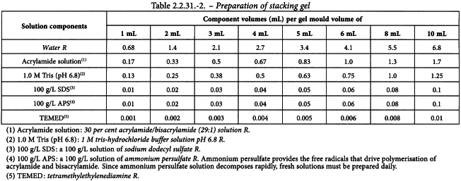
In a conical flask, prepare the appropriate volume of solution containing the desired concentration of acrylamide, using the values given in Table 2.2.31.-2. Mix the components in the order shown. Where appropriate, before adding the ammonium persulfate solution and the TEMED, filter the solution if necessary under vacuum through a cellulose acetate membrane (pore diameter 0.45 µm). Keep the solution under vacuum, while swirling the filtration unit, until no more bubbles are formed in the solution. Add appropriate amounts of ammonium persulfate solution and TEMED as indicated in Table 2.2.31.-2. Swirl and pour immediately into the gap between the 2 glass plates of the mould directly onto the surface of the polymerised resolving gel. Immediately insert a clean polytetrafluoroethylene comb into the stacking gel solution, being careful to avoid trapping air bubbles. Add more stacking gel solution to fill the spaces of the comb completely. Leave the gel in a vertical position and allow to polymerise at room temperature.
Preparation of the samples
Unless otherwise stated in the specific monograph, the samples can be prepared as follows:
Preparation of the samples (non-reducing conditions) Mix equal volumes of a mixture comprising water R plus the preparation to be examined or the reference preparation, and concentrated SDS-PAGE sample buffer R.
Preparation of the samples (reducing conditions) Mix equal volumes of a mixture comprising water R plus the preparation to be examined or the reference preparation, and concentrated SDS-PAGE sample buffer for reducing conditions R containing 2-ME (or DTT) as the reducing agent.
The concentration prescribed in the monograph can vary depending on the protein and staining method.
Sample treatment: keep for 5 min in a boiling water-bath or in a block heater set at 100 °C, then cool. The temperature and time in the monograph may vary as protein cleavage may occur during the heat treatment.
Mounting the gel in the electrophoresis apparatus and electrophoretic separation
After polymerisation is complete (about 30 min), remove the polytetrafluoroethylene comb carefully. Rinse the wells immediately with water or with the SDS-PAGE running buffer R to remove any unpolymerised acrylamide. If necessary, straighten the teeth of the stacking gel with a blunt hypodermic needle attached to a syringe. Remove the clamps on one short side, carefully pull out the tubing and replace the clamps. Proceed similarly on the other short side. Remove the tubing from the bottom part of the gel. Mount the gel in the electrophoresis apparatus. Add the electrophoresis buffers to the top and bottom reservoirs. Remove any bubbles that become trapped at the bottom of the gel between the glass plates. This is best done with a bent hypodermic needle attached to a syringe. Never pre-run the gel before loading the samples, since this will destroy the discontinuity of the buffer systems. Before loading the sample carefully rinse each well with SDS-PAGE running buffer R. Prepare the test and reference solutions in the recommended sample buffer and treat as specified in the individual monograph. Apply the appropriate volume of each solution to the stacking gel wells.
Start the electrophoresis using the conditions recommended by the manufacturer of the equipment. Manufacturers of SDS-PAGE equipment may provide gels of different surface area and thickness and electrophoresis running time and current/voltage may vary in order to achieve optimal separation. Check that the dye front is moving into the resolving gel. When the dye is near the bottom of the gel, stop the electrophoresis. Remove the gel assembly from the apparatus and carefully separate the glass plates. Remove the spacers, cut off and discard the stacking gel and immediately proceed with staining.
5-2 SDS-page - GRADIENT CONCENTRATION GELS
Gradient gels (resolving gels) are prepared with an increasing concentration of acrylamide from the top to the bottom. Preparation of gradient gels requires a gradient-forming apparatus. Ready-to-use gradient gels are commercially available with specific recommended protocols.
Gradient gels offer some advantages, as some proteins which co-migrate on fixed-concentration gels can be resolved within gradient gels. During electrophoresis, the proteins migrate until the pore size prevents further progress and a stacking effect therefore occurs, resulting in sharper bands. As shown in Table 2.2.31.-3, gradient gels also allow separation of proteins with a wider range of molecular masses compared to a single fixed concentration gel.
The table gives suggested compositions of the linear gradient, relating the range of acrylamide concentrations to the appropriate protein molecular mass ranges. Note that other gradient shapes (e.g. concave) can be prepared for specific applications.

Gradient gels are also used for the determination of molecular mass and protein purity.
5-3 DETECTION OF PROTEINS IN GELS
Coomassie and silver staining are the most common protein staining methods and are described in more detail below. Several other commercial stains, detection methods and commercial kits are available. For example, fluorescent stains are visualised using a fluorescent imager and often provide a linear response over a wide range of protein concentrations, often several orders of magnitude depending on the protein.
Coomassie staining has a protein detection level of approximately 1 µg to 10 µg of protein per band. Silver staining is the most sensitive method for staining proteins in gels and a band containing 10 ng to 100 ng can be detected. These figures are considered robust in the context of these gels. Improved sensitivity of 1 or 2 orders of magnitude has sometimes been reported in the literature.
Coomassie staining responds in a more linear manner than silver staining; however, the response and range depend on the protein and development time. Both Coomassie and silver staining can be less reproducible if staining is stopped in a subjective manner, i.e. the point at which the staining is deemed satisfactory. The use of dynamic ranges of reference proteins is very important as they help assess the intra-experimental sensitivity and linearity. All gel staining steps are carried out while wearing gloves, at room temperature, with gentle shaking (e.g. on an orbital shaker platform) and using any convenient container.
Coomassie staining
Immerse the gel in a large excess of Coomassie staining solution R and allow to stand for at least 1 h. Remove the staining solution.
Destain the gel with a large excess of destaining solution R. Change the destaining solution several times, until the stained protein bands are clearly distinguishable on a clear background. The more thoroughly the gel is destained, the smaller is the amount of protein that can be detected by the method. Destaining can be speeded up by including a few grams of anion-exchange resin or a small sponge in the destaining solution R.
NOTE: the acid-alcohol solutions used in this procedure do not completely fix proteins in the gel. This can lead to losses of some low-molecular-mass proteins during the staining and destaining of thin gels. Permanent fixation is obtainable by allowing the gel to stand in a mixture of 1 volume of trichloroacetic acid R, 4 volumes of methanol R and 5 volumes of water R for 1 h before it is immersed in the Coomassie staining solution R.
Silver staining
Immerse the gel in a large excess of fixing solution R and allow to stand for 1 h. Remove the fixing solution, add fresh fixing solution and incubate either for at least 1 h or overnight, if convenient. Discard the fixing solution and wash the gel in a large excess of water R for 1 h. Soak the gel for 15 min in a 1 per cent V/V solution of glutaraldehyde R. Wash the gel twice for 15 min in a large excess of water R. Soak the gel in fresh silver nitrate reagent R for 15 min, in darkness. Wash the gel three times for 5 min in a large excess of water R. Immerse the gel for about 1 min in developer solution R until satisfactory staining has been obtained. Stop the development by incubation in the blocking solution R for 15 min. Rinse the gel with water R.
5-4 RECORDING OF THE RESULTS
Gels are photographed or scanned while they are still wet or after an appropriate drying procedure. Currently, gel scanning systems with data analysis software are commercially available to immediately photograph and analyse the wet gel.
Depending on the staining method used, gels are treated in a slightly different way. For Coomassie staining, after the destaining step, allow the gel to stand in a 100 g/L solution of glycerol R for at least 2 h (overnight incubation is possible). For silver staining, add to the final rinsing a step of 5 min in a 20 g/L solution of glycerol R.
Drying of stained SDS polyacrylamide gels is one of the methods used to obtain permanent documentation. This method frequently results in the cracking of gel during drying between cellulose films.
Immerse 2 sheets of porous cellulose film in water R and incubate for 5 min to 10 min. Place one of the sheets on a drying frame. Carefully lift the gel and place it on the cellulose film. Remove any trapped air bubbles and pour a few millilitres of water R around the edges of the gel. Place the second sheet on top and remove any trapped air bubbles. Complete the assembly of the drying frame. Place in an oven or leave at room temperature until dry.
5-5 MOLECULAR-MASS DETERMINATION
Molecular masses of proteins are determined by comparison of their mobilities with those of several marker proteins of known molecular weight. Mixtures of pre-stained and unstained proteins with precisely known molecular masses blended for uniform staining are available for calibrating gels. They are available in various molecular mass ranges. Concentrated stock solutions of proteins of known molecular mass are diluted in the appropriate sample buffer and loaded on the same gel as the protein sample to be examined.
Immediately after the gel has been run, the position of the bromophenol blue tracking dye is marked to identify the leading edge of the electrophoretic ion front. This can be done by cutting notches in the edges of the gel or by inserting a needle soaked in India ink into the gel at the dye front. After staining, measure the migration distances of each protein band (markers and unknowns) from the top of the resolving gel. Divide the migration distance of each protein by the distance travelled by the tracking dye. The normalised migration distances are referred to as the relative mobilities of the proteins (relative to the dye front), or RF. Construct a plot of the logarithm of the relative molecular masses (Mr) of the protein standards as a function of the RF values. Unknown molecular masses can be estimated by linear regression analysis (or more accurately by non-linear regression analysis) or interpolation from the curves of log Mr against RF if the values obtained for the unknown samples are positioned along the approximately linear part of the graph.
5-6 VALIDATION OF THE TEST
The test is not valid unless the target resolution range of the gel has been demonstrated by the distribution of appropriate molecular mass markers, e.g. across 80 per cent of the length of the gel. The separation obtained for the expected proteins must show a linear relationship between the logarithm of the molecular mass and the RF. If the plot has a sigmoidal shape, then only data from the linear region of the curve can be used in the calculations. Additional validation requirements with respect to the test sample may be specified in individual monographs.
Sensitivity must also be validated. A reference protein control corresponding to the desired concentration limit that is run in parallel with the test samples can serve to establish system suitability.
5-7 QUANTIFICATION OF IMPURITIES
SDS-PAGE is often used as a limit test for impurities. When impurities are quantified by normalisation to the main band using an integrating densitometer or image analysis, the responses must be validated for linearity. Note that depending on the detection method and protein as described in the introduction of section 5-3, the linear range can vary but can be assessed within each run by using one or more control samples containing an appropriate range of protein concentration.
Where the impurity limit is specified in the individual monograph, a reference solution corresponding to that level of impurity should be prepared by diluting the test solution. For example, where the limit is 5 per cent, a reference solution would be a 1:20 dilution of the test solution. No impurity (any band other than the main band) in the electropherogram obtained with the test solution may be more intense than the main band obtained with the reference solution.
Under validated conditions, impurities may be quantified by normalisation to the main band using an integrating densitometer or by image analysis.